

SWRO membrane array and Stage Design
In a seawater reverse osmosis (SWRO) system, membrane selection is only one part of the overall design. How the membrane elements are arranged inside pressure vessels and how those vessels are divided into stages can have a direct impact on feed flow distribution, recovery, pressure management, permeate production, and concentrate handling.
For Seawater Desalination Equipment, a properly designed membrane array is not simply a matter of installing as many membrane vessels as possible. The system needs to provide suitable hydraulic conditions for each membrane element while maintaining reasonable pressure, flow velocity, recovery, and water quality throughout the process.
Understanding membrane array and stage design is therefore important when designing a new SWRO plant, expanding an existing system, or selecting customized Seawater Desalination equipment.
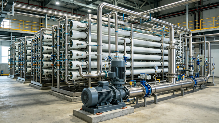
An SWRO membrane array refers to the arrangement of RO pressure vessels and membrane elements within the desalination system.
A typical pressure vessel contains several membrane elements connected in series. Seawater enters one end of the vessel and passes through the membrane elements under high pressure. A portion of the water permeates through the membrane and becomes product water, while the remaining concentrated seawater continues toward the vessel outlet.
Several pressure vessels can then be connected hydralically to form a membrane array.
The complete arrangement normally includes:
High-pressure feed piping
RO pressure vessels
Membrane elements
Permeate collection piping
Concentrate piping
Interstage piping where applicable
Pressure and flow instrumentation
Valves and control components
The exact configuration depends on feedwater salinity, required production capacity, membrane specifications, target recovery, operating pressure, and project conditions.
Water does not flow through every membrane element under exactly the same conditions.
As seawater passes through successive membrane elements, water is removed as permeate while salts remain concentrated in the feed stream. The concentrate therefore becomes progressively more concentrated along the flow path.
This creates changes in:
Feedwater salinity
Osmotic pressure
Available net driving pressure
Permeate flow
Concentrate flow
Membrane flux
A well-designed membrane array needs to account for these changes.
If the array is poorly matched to the design conditions, some membrane elements may receive excessive flow while others operate under less favorable conditions. Uneven hydraulic conditions can affect membrane performance and may increase the risk of fouling or scaling.
For this reason, membrane array design should be based on hydraulic and process calculations rather than simply the number of membrane elements required to reach the target capacity.
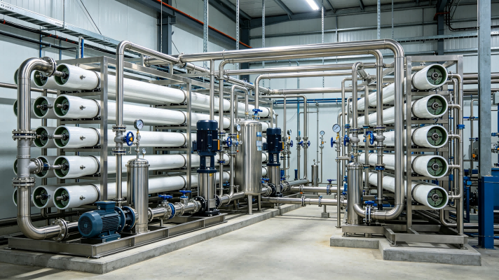
A single-stage SWRO system generally sends the high-pressure feedwater through one main group of membrane pressure vessels before the concentrate leaves the RO system.
This configuration can be suitable for certain seawater conditions and production requirements.
The main advantage is a relatively straightforward process arrangement. Feedwater distribution, pressure control, permeate collection, and concentrate discharge can be easier to manage compared with a more complex multi-stage configuration.
However, the achievable recovery may be limited by feed salinity, membrane operating conditions, and concentrate osmotic pressure.
As water passes through the membrane array, the remaining seawater becomes increasingly concentrated. At higher recovery, the osmotic pressure of the concentrate rises, reducing the effective driving force available for further permeate production.
Therefore, simply increasing recovery is not always an appropriate way to increase system efficiency.
A two-stage SWRO arrangement divides the membrane vessels into two groups.
The concentrate from the first stage is directed to the second stage, where additional water is recovered.
This arrangement can improve the utilization of the feed stream and allow the system to achieve a higher overall recovery than a simple single-stage configuration under suitable design conditions.
A simplified process can be represented as:
Seawater Feed → High-Pressure Pump → First-Stage Membrane Array → Second-Stage Membrane Array → Concentrate Discharge
Permeate from the membrane vessels is collected separately and sent toward the downstream product-water treatment system.
The number of pressure vessels in each stage does not necessarily have to be equal. In many designs, the first stage contains more vessels than the second stage because the feed flow decreases as water is recovered.
This arrangement helps maintain suitable flow conditions through the system.
The basic principle behind a staged array is flow reduction.
At the beginning of the RO process, the feed flow is relatively high. As permeate is removed, the concentrate flow becomes progressively lower.
If every section of the membrane array had the same number of pressure vessels, the hydraulic loading could become less suitable toward the concentrate end.
A staged arrangement allows the number of vessels to be reduced as the concentrate flow decreases.
For example, an array might use a larger number of pressure vessels in the first stage and fewer vessels in the second stage. The exact ratio depends on the membrane manufacturer's design software, feedwater conditions, recovery target, and required permeate quality.
The goal is to create a balanced system in which membrane elements operate within their recommended design ranges.
The pressure vessel is another important part of SWRO array design.
Multiple membrane elements can be installed in a single pressure vessel. These elements are connected in series, allowing the concentrate from one element to become the feed to the next element.
This arrangement reduces the amount of external piping required while providing a compact membrane assembly.
However, the membrane element position inside the vessel matters.
The first element generally sees the highest feed flow and the lowest feed salinity within that pressure vessel. Downstream elements receive increasingly concentrated water and lower flow.
As a result, membrane flux and operating conditions can vary from the first element to the last element.
A suitable array design aims to keep these variations within acceptable limits.
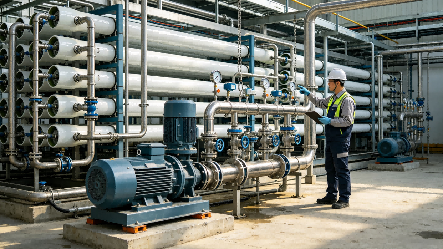
Flow distribution is one of the practical issues that engineers need to consider when designing an SWRO membrane array.
The high-pressure pump supplies seawater to the membrane system, but the flow must then be distributed among multiple pressure vessels.
If the piping configuration creates significant hydraulic imbalance, different pressure vessels may receive different feed flows.
Uneven flow can result in different membrane loading conditions and may influence:
Permeate production
Membrane flux
Fouling tendency
Pressure drop
Membrane service life
Proper header sizing, branch arrangement, valve selection, pipe diameter, and hydraulic balancing can therefore make a significant difference to system performance.
Recovery refers to the percentage of feedwater converted into permeate.
For example, if an SWRO system receives 100 units of feedwater and produces 40 units of permeate, the overall recovery is 40%.
The remaining 60 units leave the system as concentrate.
Recovery is closely related to membrane array design because higher recovery means the concentrate becomes more concentrated.
As salinity increases, osmotic pressure also increases. This reduces the net driving pressure across the membrane and can make additional water recovery more difficult.
High recovery may also increase the potential for scaling if the feedwater contains minerals that approach their solubility limits.
Therefore, membrane array design should balance water recovery against membrane operating conditions and concentrate chemistry.
Pressure does not remain constant throughout an SWRO membrane array.
Pressure decreases because of several factors, including membrane permeation and hydraulic pressure loss through piping and membrane elements.
At the same time, the osmotic pressure of the feed stream generally increases as water is removed.
The effective driving force for permeation can therefore change considerably from the feed end to the concentrate end.
Engineers need to consider these pressure relationships when determining the number of membrane elements, pressure vessels, stages, and operating pressure.
A design that looks adequate based only on pump discharge pressure may not provide uniform membrane performance throughout the complete array.
The membrane array also has a relationship with energy consumption.
SWRO requires high-pressure pumping because seawater has significant osmotic pressure. The high-pressure pump normally represents one of the major energy-consuming components in the process.
A properly designed membrane array can help use the available pressure more effectively and reduce unnecessary hydraulic losses.
Energy-recovery devices can further improve system efficiency by transferring energy from the high-pressure concentrate stream back to the feedwater side.
The selection and configuration of energy-recovery equipment should be considered together with membrane array design rather than treated as a completely separate part of the system.
Good membrane array design cannot compensate for inadequate pretreatment.
SWRO membranes are sensitive to suspended solids, colloids, microorganisms, organic matter, and scaling compounds. If pretreatment does not adequately control these contaminants, membrane performance can deteriorate regardless of how carefully the pressure vessels are arranged.
Depending on the seawater source, pretreatment may include:
Intake screening
Coagulation and clarification
Multimedia filtration
Ultrafiltration
Microfiltration
Cartridge filtration
Chemical dosing
The appropriate pretreatment configuration depends on the actual feedwater characteristics.
For seawater Desalination Equipment, membrane array design and pretreatment design should therefore be developed as parts of the same process system.
When engineers determine the appropriate membrane array, they normally review a combination of process parameters.
Important inputs include:
Feedwater salinity: Higher salinity generally means higher osmotic pressure and may require greater operating pressure.
Feedwater temperature: Temperature affects water viscosity and membrane permeability, which influences permeate flow.
Required permeate flow: The target production determines the approximate membrane area and number of pressure vessels.
Recovery: Higher recovery changes concentrate salinity and osmotic pressure.
Membrane specifications: Different membrane elements have different operating ranges and performance characteristics.
Pressure limits: Pumps, pressure vessels, membranes, piping, and valves all need to operate within their specified limits.
Water quality: Feedwater composition affects pretreatment requirements and scaling or fouling risks.
These parameters should be evaluated together instead of selecting the membrane quantity based only on nominal production.
Consider a conceptual SWRO system designed with two membrane stages.
The first stage receives the main high-pressure seawater feed and contains a larger number of pressure vessels. Permeate is collected from these vessels, while the remaining concentrate moves toward the second stage.
The second stage contains fewer pressure vessels because the concentrate flow is lower.
This can be represented simply as:
High-Pressure Feed
↓
First-Stage RO Array
→ Permeate
↓
Second-Stage RO Array
→ Permeate
↓
Concentrate
This is only a conceptual arrangement. Actual vessel numbers and staging ratios must be determined from site-specific feedwater conditions, membrane performance data, target recovery, and hydraulic calculations.
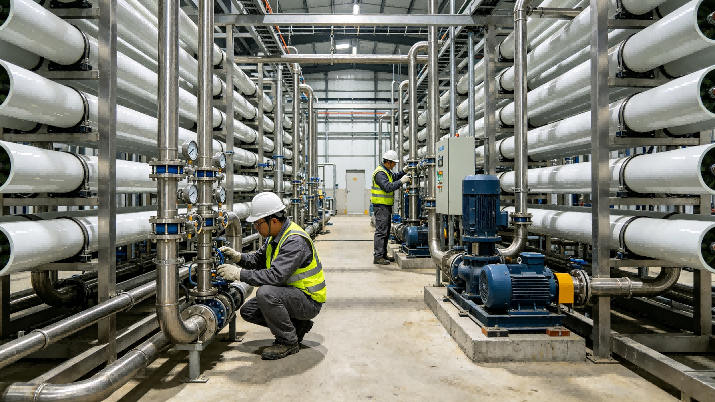
Once the system is operating, monitoring individual parameters helps confirm whether the array is performing as expected.
Operators may track:
Feed pressure
Interstage pressure
Concentrate pressure
Feed flow
Permeate flow
Concentrate flow
Feed conductivity
Permeate conductivity
Differential pressure
Feedwater temperature
Changes in these parameters can provide useful information about the condition of the membrane system.
For example, a gradual increase in differential pressure may indicate fouling or flow restrictions. A reduction in normalized permeate flow may indicate membrane performance changes after accounting for temperature and other operating variables.
Monitoring should therefore focus on trends rather than a single reading.
Not every seawater desalination project needs the same membrane array.
A small island water supply system, an offshore platform, a coastal industrial plant, and a municipal desalination facility can have very different feedwater conditions and production requirements.
A customized SWRO system may need to consider:
Daily water demand
Peak water demand
Intake configuration
Seawater salinity
Available installation space
Electricity supply
Required product-water quality
Concentrate discharge conditions
Maintenance requirements
For containerized systems, the arrangement also needs to consider equipment footprint, pipe routing, access for membrane replacement, and transportation limitations.
This is why project-specific engineering is often more appropriate than applying one standard membrane array to every installation.
SWRO membrane array and stage design determine how seawater moves through the membrane system and how the available membrane area is used.
The arrangement of pressure vessels, membrane elements, stages, headers, and piping influences flow distribution, pressure loss, recovery, permeate production, and concentrate conditions.
A well-designed system considers these factors together with seawater temperature, salinity, pretreatment, membrane specifications, energy requirements, and the actual production target.
For seawater desalination equipment, the objective is not simply to install more membrane elements. The objective is to create a balanced hydraulic and process configuration that keeps the membranes operating within appropriate conditions while delivering the required quantity and quality of product water.
By evaluating membrane array configuration and stage design during the early engineering stage, SWRO projects can establish more predictable operating conditions and provide a practical foundation for long-term membrane management.
Этот веб-сайт использует файлы cookie, чтобы обеспечить вам максимально эффективное использование нашего веб-сайта.
 English
 Portugues
 Français
 العربية
 ไทย
ไทย Indonesia
 Melayu
 Tiếng Việt
 中文
中文 қазақ
қазақ עִברִית
 မြန်မာ
 ພາສາລາວ
 Filipino
 o'zbek
 Кыргызча
 тоҷикӣ
 ខ្មែរ
ខ្មែរ Türkmenler


 телефон
Комментарий
(0)